Catalogue, User manual for Speed Radar with Camera
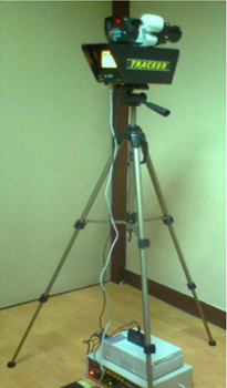
The Tracker system consists of a speed radar gun above to the Video Camera. This is capable of storing Video Picture of the Vehicle with speed, date, time by using an DVR.
The Video can be downloaded into a computer with windows for archiving and RTO Records.
| Specification |
| Type: |
Hand Held Vehicle Speed detection equipment |
| Speed Measurement |
| Range: |
17 to 185 Kmph |
| Accuracy: |
+/- 1 Kmph |
| Maximum Operating range: |
>700 meters |
Display: |
LED display |
Temperature: |
-30 to 60 degree Celsius |
| Power supply: |
Rechargeable battery with charger for 6 hours operation and 100 Monochrome prints. |
| Colour Camera: |
Sony FCB EX 980CP |
| Zoom: |
20X optical and 6X digital total 26X |
| Horizontal resolution: |
460 TV lines |
| Digital Video Recorder: |
Continuous Colour Video recording with date and Time for Minimum of 20 hours. |
| Monochrome Printer: |
Sony Monochrome Video Printer capable of printing at site with Date, Time, Speed at the top of the screen Without interfering with the number plate area. |
| Stand: |
Foldable Telescopic Tripod with height greater than 1.5 Meters |
| Accessories: |
Carry case, cables etc. |
CONTENTS
1. Unpacking system
2. Assembling Tripod
3. Connecting Tracker Camera to Print System
4. Connecting Foot switch to Tracker Camera
5. On road user instruction
6. Tracker Camera overview
7. Print system overview
8. Sony Printer overview
9. DVR overview
Unpacking System
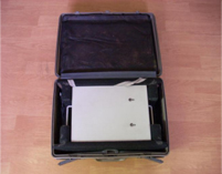
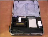
The Tracker system is supplied in two compact Suitcases. One suitcase contains the Print System and the second suitcase contains Camera with Speed Radar Gun ,Printer, Tripod DVR and associated accessories
Carefully remove the Print system from its suitcase and keep it on a reasonably flat surface. Without giving any connections to the Print System, switch the print system ON by pressing the power switch located on the left bottom portion of the front panel. Check if both the green LED Lamps (12volt and 24 volt) are illuminated. If any one of the Led is off the Print System will require charging. (Refer to Print System Overview). Switch Off the Print System.
Open the second suitcase.
The following Items are placed in the suitcase.
a) Tripod. (Inside a Bag)
b) High-resolution Sony Monochrome video Graphic Printer.
c) Tracker Camera with Radar Gun
d) DVR with Charger and Remote
e) Battery for Radar Gun.
f) Foot switch (Inside a Bag)
g) Car Charger and Battery Charger (Inside a Bag)
h) Tuning Forks (Inside a Bag )
i) Paper Roll of Radar Gun (Inside a Bag)
j) System Connecting Cables (Inside a Bag)
Remove the tripod from its bag. Spread the three legs of the tripod by pulling them outwards. Place it on a flat surface. The tripod legs can be elongated by releasing the leg wing nuts on the leg. To dismantle the tripod do the above steps in reverse order.
Mounting Tracker camera on tripod
The tripod head has a quick release head attachment. Pull the thumb release lever till it locks with a click. Turn the Tripod Head such that the up down tilt handle is pointing towards you. Mount the camera with LCD screen facing towards you, keep it firmly on the head and press the camera down gently till the thumb release latch locks with a click. A small brass lever is located near the thumb release latch; this is use for locking the thumb release latch. To lock the latch rotate the brass lever clock wise and to unlock the thumb latch rotate the brass lever anti-clockwise. To dismount the camera, unlock the Thumb release latch and pull the thumb release latch and at the same time lift the camera upwards.
Connecting Tracker Camera to Print System
Remove the System connection cable from the suitcase. This is a round cable with two industrial 4-hole sockets on either end. One Socket should be inserted onto the camera and the other should be inserted onto the Print system. The ring nut should be rotated clock wise to hold the cable firmly. The socket can be inserted only in one direction. The direction can be identified by the depression on one side of the socket.
Connecting Foot switch to Tracker Camera
The foot switch has a 2.5-mm EP male on it. Insert this into the EP female on the Camera.
On road user instruction
Choose a straight stretch of road. Place the Tracker camera on the footpath such that it faces the traffic. Switch on the print system. Pan and Zoom on a stationary tree or some other object on the footpath such that it is clearly visible. (This may not be necessary once personnel gets accustomed to the system). Now point the Tracker towards the traffic. Choose a vehicle, which is over-speeding, and ensure that the numberplate is visible clearly. Now press the footswitch till three stars are visible on the right bottom of the screen. Release the foot switch. The printer will print the Photo.
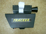
Tracker Camera overview
The Tracker camera contains the Video camera Speed detector and a sophisticated Microcontroller for the entire system. The front portion houses the video camera and the speed detector. The rear portion has a large 3.6inch Colour LCD screen, Zoom buttons and a “D” connector for adjustments by authorized technical personnel. The bottom front portion of the camera has the quick release shoe fixed permanently. The bottom rear portion has the connecting sockets and switches required for connecting the camera as mentioned below. When viewed from the bottom and LCD facing towards yourself the connection sockets numbered 1 to 4 from left to right.
1. Power ON/OFF switch for Tracker Camera.
2. Industrial 4 hole socket for Print system connection.
3. 2.5 mm EP socket for foot switch connection.
4. Limit Set switch on Left side of Camera
Start up:
Mount the Tracker camera with Radar Gun on the Tripod and give all connections to Print system, Foot switch.
Switch on the print system.
The LCD screen will flash once and after a few seconds, No AV sync will be displayed, after a few more seconds the LCD will show the Image in front of the camera. (Even after 15 seconds, if NO AV sync is displayed, send unit for service). In approximately 20 seconds the date time speed fields will be shown on the LCD. (In case the date time values are wrong, contact service for resetting date and time).
There are four buttons provided on the Camera for zoom in and zoom out, Far and Near.
The camera has an Optical zoom of 20X and digital zoom of 6X.
Pressing the Limit switch can increase the Limit speed shown in the display. For each press the Limit speed will increment by 5 Km. The button has to be pressed for approximately 1 second to increment the Limit speed.
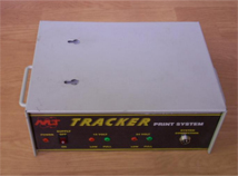
Print system overview
The print system has the following components.
1. System backup batteries for Tracker camera and Printer.
2. Charging Electronics for the system.
3. Charge indicator for 12 volts supply used by Tracker. (Front fascia).
4. System connection socket. (Industrial 4-hole socket). (Front fascia).
5. Power on switch. (Front fascia).
6. Printer connection socket 4-hole (Rear Fascia)
7. Printer connection socket 2-hole. (Rear Fascia)
8. Charging Socket. (Rear fascia).
9. Charging switch . (Rear fascia).
Print System Front Fascia
1. Power on switch
2. 12 volt power status LED Red and Green
3. Tracker Camera connection socket
12 volt power status Led Red and Green
12 volt Green LED when illuminated indicates that
12-volt supply is at full charge. 12 volt Red LED when illuminated indicates that 12-volt supply charge is low.
If the Red LED Glows the system has to be charged.
System connection socket should be connected to the Tracker Camera with the cable provided.
Charging the system Rear Fascia
1. Charging socket.
2. Charging switch.
3. Fuse.
To charge the system, insert the charging cable Din plug into the charging socket. Insert the 3-pin plug into a 220volt-supply point. Switch off the power switch on the front fascia. Switch on the charging switch. Wait for approximately 8 hours for charging. After 8 hours, switch off the charging switch. Remove the charging cable. Switch on the Power switch. The 12-volt Green Led should Glow.
If the Red Led is glowing check the fuse. If blown replace it with the same type of fuse and charge the system again. If the fuse is not blown, contact service for rectification of the system.
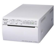
Sony Printer overview
This is placed on the top of the print system. No adjustments are required for the printer. Only operation required would be replacing paper roll when empty.
Paper roll replacement Switch on Print System.
On the Printer right topmost corner a small yellow LED is located. This LED will flash and switch off if paper roll is present. If the paper roll is empty the LED will glow. To change the printer roll press the open button located below the LED. The paper holder will open. Place the new roll such that the paper comes on the top of the paper out slot and close the printer by gently pressing the paper holder backwards. After this is done a small portion of the paper should be visible on the paper slot.
Switch off Print system.
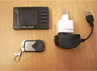
DVR overview
Print system overview
Features:
1.2.4" TFT on DVR
2.Wired and wireless version selectable
3.Internal 60MB memory, support 16GB sd card
4.Frame for 30f/s
5.Resolution:VGA(640×480)、QVGA(320×240)
6.Wireless supported:8 channel supported
7.Recharge or transmit videos to PC via USB cable
8.Wireless remote control supported
9.Time stamping on videos
10.Audio and videos for real time
11.Support 3.7V rechargeable battery
12.Dimension:85×54×17mm
|